Utilization of 3D Data in Construction Projects
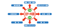
The greatest advantage of CIM is “improvement of communication among people involved in construction projects = (1) to deepen understanding (2) to prevent mistakes (3) to promote consensus building = efficiency improvement”. “By people involved in construction projects” we mean n the case of public work projects people in all positions involved in the project from the present to the near future, such as governments, construction consultants, designers, general contractors, residents who use will eventually them, maintenance workers, and people in other regions who are considering similar projects, etc. Among those people, the situation that “even if you can’t go to the site, even if you don’t have much expertise in construction, you can still talk on the same page as others” become reality, they can avoid misunderstandings, troubles, and waste by sharing mutual understanding. As a result, you can save a lot of money, and as a result, you can carry out your business more efficiently.
To Understand CIM – Basic Knowledge in Using CIM
-
【Basic knowledge of 3D】 How to express and display 3D information
First, here are basic points about 3D.
There are three ways of expressing a three-dimensional (3D) object on the display. They are “wireframe”, “surface”, and “solid”. At first glance, the three cubes below look the same, but each has a different expression method, and as a result, the workload required for the computer also differs. It is used properly according to the design stage and purpose.

Wireframe Model
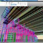
It literally means “a frame model made of wires.” Wireframe model expresses a cube with only “dots” as the vertices and “lines” as the sides. It is like a cube model made of small rolled clay (dots) and sticks (lines), with no surface or contents. Wireframes are often used in the early stages of design, where you only need to check the basic shape and don’t need to see the details yet. Since the amount of data is small, the display speed is also fast.
Surface
It is like a cube-shaped box in a way that “faces” are added to the wireframe model. Of course, not only flat surfaces but also curved surfaces can be expressed, so it is used for the purpose of expressing a concrete model by adding a surface to the designed shape and adding the texture of the material to the surface. It is like a plastic scale model with a hollow content inside.
Solid
This is a method of adding contents to “dots”, “lines”, and “faces”. In the case of a cube, it is like a full-filled “dice”. In a structure, “contents” means parts. Information such as the quality, weight, size, and contact surface of parts is also converted into data in “solid”, so various calculations and simulations become possible. But on the other hand, it takes longer time to display. Since not only we can express 3D objects richly on computer display but also perform the analysis required for design with this solid method, modern general 3D-CAD software are designed to deal with solid models.
Wireframe Model
It literally means “a frame model made of wires.” Wireframe model expresses a cube with only “dots” as the vertices and “lines” as the sides. It is like a cube model made of small rolled clay (dots) and sticks (lines), with no surface or contents. Wireframes are often used in the early stages of design, where you only need to check the basic shape and don’t need to see the details yet. Since the amount of data is small, the display speed is also fast.
Surface
It is like a cube-shaped box in a way that “faces” are added to the wireframe model. Of course, not only flat surfaces but also curved surfaces can be expressed, so it is used for the purpose of expressing a concrete model by adding a surface to the designed shape and adding the texture of the material to the surface. It is like a plastic scale model with a hollow content inside.
Solid
This is a method of adding contents to “dots”, “lines”, and “faces”. In the case of a cube, it is like a full-filled “dice”. In a structure, “contents” means parts. Information such as the quality, weight, size, and contact surface of parts is also converted into data in “solid”, so various calculations and simulations become possible. But on the other hand, it takes longer time to display. Since not only we can express 3D objects richly on computer display but also perform the analysis required for design with this solid method, modern general 3D-CAD software are designed to deal with solid models. -
【How to build 3D】 Form of application software that handles 3D information
is an image which was created after being added “depth” to a two-dimensional image like a picture drawn on a piece of paper. In design and design, this 3D (3 dimentions) is expressed on the display. As you know, the display itself is flat, but the “3D picture” that looks like a realistic solid with depth is reproduced with a use of software which deals with 3D data . There are the following types of 3D data that we see on the display.
- ● Expression: How realistic can the power of expression of the displayed image be?
- ● Precision: How much mathematical accuracy (= accuracy) is maintained in the structures and parts displayed in the images / videos?
- ● Interactiveness:How much information can be obtained when the user works on the image / video displayed on the screen?
3D CG(Three-Dimentional Computer Graphic) 
This is a 3D picture drawn by a computer. we can see it at many occasions in our daily lives. You may have seen the rendering of a building that looks exactly like the real thing. That is 3DCG. It is also widely used in the world of games, movies and commercials these days. The biggest feature of 3DCG drawings is that they can realistically express how the human eye perceives them at a glance, and the viewer can instantly grasp the image. On the other hand, it is not “accurate” like 3D CAD even if it looks real because it is drawn by combining figures by a computer according to the output size. For example when you see this type of image with a digital camera and enlarge it infinitely, unevenness appears on the curving parts of the image. Therefore, it is ideal as a rendering, but it is not suitable for accurate design.
● Please take a look at our Gallery “CG Perspective” using 3DCG.Expression Precision Interac-
tiveness◎ ○ △ 3D CAD(Three-Dimentional Computer Aided Design) 
At first glance, it looks like a picture similar to CG, but since accurate dimensional data is linked to each part of the picture, it is possible to create more precise modeling than the actual 2D drawing can. Since the data expression method is different from the above CG, even if the curve or sphere is enlarged on the display, it still can maintain the accuracy of the original shape. Of course, CAD is often used not only for structures but also for the design of personal consumer goods (digital cameras, skis, tableware, furniture), and is widely used as the most common software for handling 3D data. Expression Precision Interac-
tiveness○ ◎ △ 3D VR(Three-Dimentional Virtual Reality) 
VR is a dramatic development of CG and CAD. It is a tool that allows you to see the buildings on the display from the perspective of the real world, such as looking down the buildings from a bird’s eye, looking up from a close distance, going under or crossing the bridge. There are a wide variety of ways to use it, such as comparing landscapes, changing sunlight, examining landscapes from a specific perspective such as the driver’s seat while driving, and simulating disasters such as floods.
On the other hand, because of its high accuracy, the data size becomes so heavy that sometimes the viewpoint can’t be moved smoothly on the display, but this disadvantage will be solved by the remarkable progress of PC technology.
● The quickest way to understand VR is to look at it. Please take a look at Gallery “3D VRCG Data”.Expression Precision Interac-
tiveness○ ○ ◎ 3D CG(Three-Dimentional Computer Graphic) 
This is a 3D picture drawn by a computer. we can see it at many occasions in our daily lives. You may have seen the rendering of a building that looks exactly like the real thing. That is 3DCG. It is also widely used in the world of games, movies and commercials these days. The biggest feature of 3DCG drawings is that they can realistically express how the human eye perceives them at a glance, and the viewer can instantly grasp the image. On the other hand, it is not “accurate” like 3D CAD even if it looks real because it is drawn by combining figures by a computer according to the output size. For example when you see this type of image with a digital camera and enlarge it infinitely, unevenness appears on the curving parts of the image. Therefore, it is ideal as a rendering, but it is not suitable for accurate design.
● Please take a look at our Gallery “CG Perspective” using 3DCG.Expression: ◎
Precision: ○
Interactiveness: △3D CAD(Three-Dimentional Computer Aided Design) 
At first glance, it looks like a picture similar to CG, but since accurate dimensional data is linked to each part of the picture, it is possible to create more precise modeling than the actual 2D drawing can. Since the data expression method is different from the above CG, even if the curve or sphere is enlarged on the display, it still can maintain the accuracy of the original shape. Of course, CAD is often used not only for structures but also for the design of personal consumer goods (digital cameras, skis, tableware, furniture), and is widely used as the most common software for handling 3D data. Expression: ○
Precision: ◎
Interactiveness: △3D VR(Three-Dimentional Virtual Reality) 
VR is a dramatic development of CG and CAD. It is a tool that allows you to see the buildings on the display from the perspective of the real world, such as looking down at the VR is a dramatic development of CG and CAD. It is a tool that allows you to see the buildings on the display from the perspective of the real world, such as looking down the buildings from a bird’s eye, looking up from a close distance, going under or crossing the bridge. There are a wide variety of ways to use it, such as comparing landscapes, changing sunlight, examining landscapes from a specific perspective such as the driver’s seat while driving, and simulating disasters such as floods.
On the other hand, because of its high accuracy, the data size becomes so heavy that sometimes the viewpoint can’t be moved smoothly on the display, but this disadvantage will be solved by the remarkable progress of PC technology.
● The quickest way to understand VR is to look at it. Please take a look at Gallery “3D VRCG Data”.Expression: ○
Precision: ○
Interactiveness: △ -
【Practice of 3D】 Improving User Benefits through CIM
Users of CIM can get various convenience out of utilizing CIM.
- Significant Cost and Time Savings.
Efficiency can be expected in many aspects, such as understanding the project outline before construction, consensus building among users, and sharing information between site workers involved in actual construction.
* Click to see the enlarged image. - Maintenance Becomes Much Easier
All important historical data for maintenance such as construction details, detailed data of each part, repair / replacement record, maintenance record, etc. are stored in CIM data as attributes, so even after many years, all necessary information can be found quickly and easily. You can instantly pull it out and check it with a single click. In the case of public works projects, when you need to refer to a certain past civil engineering work, you can get to know the details of the construction plan without having to research and investigate from scratch.* Click to see the enlarged image.
- Significant Cost and Time Savings.
SLDI’s CIM – Introducing its Features and Practical Examples
SLDI president & CEO Aritomo Ueda was employed by a construction consulting company in the United States in 1995, and practiced effective utilization methods in the civil engineering and construction fields using 3D CAD and 3D CG, which then could be described as the prototype of CIM, at the site in the United States. Under his leadership, based on the idea that “visualized things are most convincing to people”, SLDi has been working on utilization of technology of 2D and 3D visual data from the its foundation to the present. In addition, he has been involved in many construction projects which are the basis of CIM utilization, such as planning work for landscapes, parks, environmental assessments, consensus building among residence, design work for bridges and roads, construction management work at construction sites, etc.
-
【Feature 1】 How to Understand Landscape Design CIM
SLDI takes the position of “consulting” rather than being just a 3D modeler or CG creator and has accumulated sufficient and necessary amount of knowledge and experience in civil engineering field for CIM. For example, even with a single road, the road structure must be constructed based on basic information on the road structure such as Clothoid curves and bank. Visual data used in CIM cannot be produced without structural knowledge and experience, and data created without that knowledge and experience is meaningless to users. Based on the reality of CIM, SLDI can produce and consult “visual data that can be used in the field”. The data SLDI produces has the following advantages:
- Construction of 3D Information (3D Data) (Modeling)
By making full use of all the methods mentioned above (wireframe, surface, solid), the structure is captured from all angles. Therefore thorough verification, analysis and design become possible. - Expression / Display Method
SLDI has the technology and practical know-how to make full use of all application software mentioned above (3DCG, 3D-CAD, 3DVR), so SLDI can create data that anyone involved in the project can understand and understand. - Addition of Attribute Information (Specs)
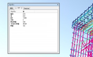
Since detailed attribute information of parts used for construction can be linked to a 3D model, waste of time and cost regarding maintenance can be reduced.
SLDI Other Companies Representation Method of Modeling Adopted Wireframe, Surface, Solid Mainly solid only Software Used for Expression CG and CAD and VR, or hybrid CG or CAD or VR Benefits for Users Since you can talk technically, the burden on users is reduced. You have a hard time understanding the instructions. Background Civil engineering construction engineers who work after understanding engineering and having practical experience. Artists or designers who create things with a gorgeous appearance without an engineering understanding. Representation Method of Modeling Adopted
SLDI: Wireframe, Surface, Solid
Other Companies: Mainly solid onlySoftware Used for Expression
SLDI: CG and CAD and VR, or hybrid
Other Companies: CG or CAD or VRBenefits for Users
SLDI: Since you can talk technically, the burden on users is reduced.
Other Companies: You have a hard time understanding the instructions.Background
SLDI: Civil engineering construction engineers who work after understanding engineering and having practical experience.
Other Companies: Artists or designers who create things with a gorgeous appearance without an engineering understanding. - Construction of 3D Information (3D Data) (Modeling)
-
【Feature 2】 Data Security Measures
CIM is a package that collects data from all aspects of the project, so security measures are essential. SLDI’s trained professionals are in charge of security, so you can rest assured.
Since SLDI’s staff builds 3D CAD / CG / VR data, it is safe to keep confidential information. It is possible to instruct the government agencies and users how to handle data.
-
【Feature 3】 Maintenance / Education
Even after delivery to the customer, SLDI will support 3D data update (charged), backup storage, software upgrade necessary for data utilization, advice on how to utilize, and other troubleshooting through maintenance service.
-
【Examples of utilization】SLDI’s CIM
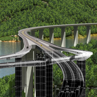
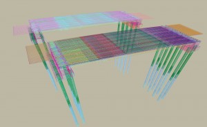
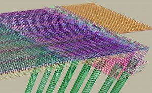
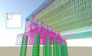
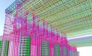
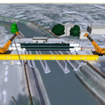
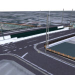
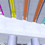
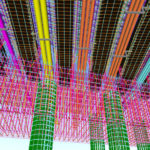
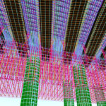
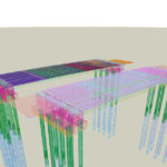
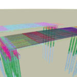
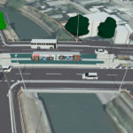
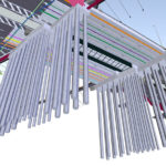
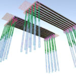
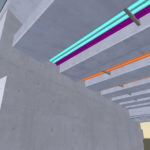
【These images are posted with permission from Toyama City】Bridge Beam
